Level – Intermediate:
Introduction:
This is a fairly old tutorial, as you may notice by the version of Lightwave used! However, the principles are exactly the same in newer versions, and indeed you should be able to apply the ideas presented with pretty much any CGI software.
Original introduction
I have seen many rather poor attempts to make convincing ringed planets, and thought it might be a good idea to tell you how I do it. I rate it as intermediate in level, as I am not going to explain mouse click and numeric values. You should be familiar with making spheres and disks, and applying image based texture maps. I have done this tutorial as one long page, so it is easier for you to print. It should work with any version of Lightwave from 5.6 onward, and the ideas should also be easy to adapt to any other modern 3D graphics package.
The planet has 2 main components, the globe of the planet itself, and the ring system.
The planet:
1. Start modeller, and make a ball, about 1 metre radius. It should not be a perfect sphere, but should be slightly squashed on the Y axis. Gas giant planets in our solar system spin fast enough to deform, and your planet will look more convincing if it is slightly flattened. The technical term is ‘oblateness’. Try a radius of 1 in the X and Z dimensions, and 0.9 in the Y dimension. A tessellated sphere spreads the polygons nice and evenly, here I am using a level 9 sphere. You may want to use a finer sphere if you plan on getting close.
2. When you have made your globe, give the surface a name, I am using ‘PLANETSURFACE’. Turn on smoothing too.
The base texture.
3. Our starting point is going to be a picture of a real planet. Jupiter, Saturn and Neptune work well – find a nice clear picture using Google or visit the NASA web site. I’m going to start with a picture of Jupiter I found here:
http://nssdc.gsfc.nasa.gov/image/planetary/jupiter/hst_jupiter_storms.jpg
Use this one, or your own choice, and save it to your hard drive.
We are going to take a very thin vertical strip, and wrap it around the planet. If its very thin, we won’t have to worry about a seam where the image joins up. So, rotate your planet if necessary, so its the right way up, and slice out a thin vertical sliver of image. You can see mine as a thin strip to the right of this paragraph, right click on it and save if you want to use it).
If you wish you can adjust the image at this point – for a science fiction world stronger colours often look good, or you can adjust the HUE in your preferred graphics package, for a more alien effect. But this is easily done at a later stage, and I recommend waiting for now.
4. Fire up the surface editor, and select the diffuse channel.
Apply the image as a cylindrical map on the Y axis, and auto size it. To keep things nice and sharp, I have turned off pixel smoothing.
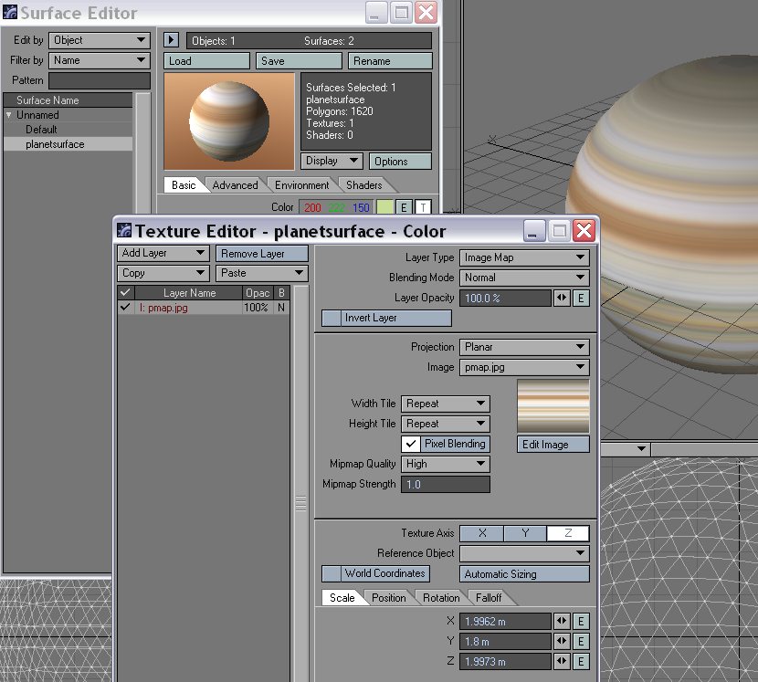
You now have something that’s beginning to look like a planet! Be aware that open GL textures often mess up the seams on an image map, so if you are worried by the look, it may be useful to make a test render.
Fine tuning the planet.
There are a couple of other things we need to do to make the planet look good.
5. The terminator. The line between the lit and the dark parts should be sharper than the Lightwave default. You can control this with the ‘diffuse sharpness’ control on the advanced surface tab. I recommend a setting of 40%
6. Disturbances. Our bands are VERY regular, and this is not realistic. If you look at the bands of Jupiter in particular, the bands are churned up on a fine scale. We can achieve this effect in Lightwave by adding a DISPLACEMENT TEXTURE to mix things up a bit.
Displacement textures are not very intuitive – adjusting the scale does not change the scale of the effect. It is always scaled to 1 metre. To reduce the scale of the effect, adjust the layer opacity. Something like 1 or 2 percent can look good. Displacements won’t show in the open GL view, but does show in the texture preview.
If you have version 10+, you can use VPR to see exactly what’s going on. VPR is a very useful feature for times like this, when you are experimenting.
So you can see it in this example, I set it quite strong. Note the order of the layers! Experiment with different procedural textures to get the result you like.
It can be effective to make the displacement texture fade on the Y axis, so that the poles are less disturbed than the equator. Note that displacement textures seem to work on a fixed scale of metres, so if you made your planet too big in stage 1, the displacements will not show!
This roughing up will also mean you can see the planet rotating, because its not totally even.
Here’s our churned up planet.
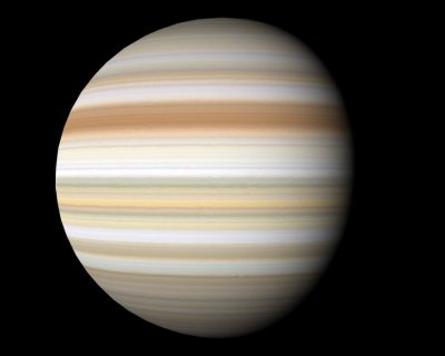
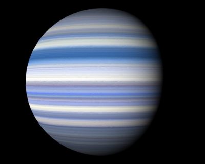
7. Fine Tuning. We are nearly done. At this stage you may want to adjust your image map. For example, the planets a normally roughly symmetrical north to south, or you might want to soften the image to weaken fine detail in the bands, or adjust the colour in the mid part to produce an equatorial belt. If you adjust the hue and saturation, (which can be done inside Lightwave, from the Image Edit panel), you can easily make a completely new planet, like this:
The Ring System.
Now for the magnificent ring system. Save your work so far, and go to a new layer in Modeller. (Not essential, but keeps things simple.) We want to create a really intricate ring system, with tons of detail, but without using huge numbers of polygons, or vast image maps. The technique I will show you does exactly that.
8. Make the rings. We are going to add a very, very thin ring system, in the shape of a washer, or disk with a hole in it. You can choose your own sizes, but I suggest an inner radius of 30% more than the planet, and an outer radius of a bit over double. The disk should be VERY thin. Note that the ring system of Saturn is hundreds of thousands of miles across, but only metres thick.
If you view the tip of the ring system at a shallow angle, it will seriously exaggerate the polygon edges of the rings, so use a LOT of segments for the disk. Here I am using 3600, making each one 0.1 degrees around. If you plan on getting very close, use more.
In LW 8.5+ you can make the washer shape with the WEDGE tool, which you will find under “create / more / wedge”. (For some reason it calls itself Annulus once launched). Here are the settings I used:
Give it a surface called RINGS. And while we are at it, name your layers, and parent the rings layer to the planet layer.
Getting ready for the texture.
9. We really don’t want to do a texture like an archery target, it would need to be HUGE to work well, and would use loads of memory. So we are going to use a trick. Make sure you are in points mode, and select all the points the inside of the ring system, like so:
Now open up the numeric window, and the move tool. Move those points up along the Y axis by a small amount, (but a good bit more than your ring thickness). For my example. 0.1 mm works well.
Why are we doing this? Well, our ring system is now a very short truncated cone. Here’s an exaggerated example, to show you what’s going on more clearly:
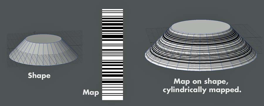
This means we can now apply a thin vertical strip of image from top to bottom, and it will run around our object, making rings for us.
10. The texture.
We are now going to repeat our trick with the planet for the rings. There are several things you can do here, but what we want to end up with is a grey image that is a narrow vertical strip, with lots of fine detail. One obvious source is an image of Saturn’s rings. I found a good image here:
http://photojournal.jpl.nasa.gov/catalog/PIA06537
(Click the small image for a larger version)
I rotated it, so I could get a nice vertical thin slice, and got my map, like this. You may need to convert your image to grey scale. For reasons that will become clear later, it’s good to take a second slice of a different chunk at this time, (maybe smaller). Again you want a very thin one, ideally one pixel wide. Get it as thin as you can then resize the image with your preferred image editor.
Now apply it as we applied the image to the planet, as an auto sized cylindrical image map in the Y axis. Again, be sure to turn off Pixel Blending on the image map, to keep the rings sharp.
As you can see, it’s beginning to look like a ringed planet!
Note! My ring map came out dark, so I inverted it to make it brighter. If your image editor has an “equalise” function, this is great way to get a good even spread of brightness values.
11. Consistent brightness. Remember how we adjusted the terminator brightness for the planet? The rings are similar, but the effect is even more pronounced, so go to the advanced tab and set the edge brightness to 100%. This will make the rings the same brightness whatever the angle of the Sun, (unless the light is exactly edge on).
Let’s have a test render:
12. Transparency. That’s all very well, but the obvious thing lacking now is that the rings are completely opaque, so we can’t see the planet through the rings, and we don’t get those elegant detailed shadows of the rings on the planet. We need a transparency map.
Rendering notes.
13 You are probably tempted to do some rendering round about now. Here are some notes on how to make it look good.
You want the detailed shadows to show up on the planet, so make sure ray trace shadows is on. You will also need ray trace transparency on, for the same reason. Make sure that you are using a distant light for the Sun, and that it is not shining along the edge of the rings. Also make sure that your ambient light is set to 0%, so the Sun is the only light source.
14. The transparency map. We now need to apply a transparency map. The easy option is to use the same image we used for the rings, but you will get a lot more subtle detail if you use a different image – this is why we grabbed one a few steps back. Go to the transparency channel of the ring texture, and apply your other image as the map. (You can similarly add complexity if you simply reverse the first map, or take a chunk out of it)
Try a test render!
Let’s get in closer, at a nice shallow angle to show off the details:
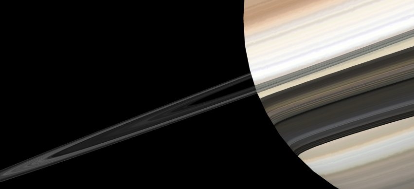
The transparency map will probably benefit from some adjustments, and this can easily be done inside Lightwave. Go to the image editor, and select the edit tab. If we combine a transparency map with the image map, we may end up with a lot of dark areas. Try increasing the brightness of the image transparency maps here. If you want to reduce the level of fine detail, try increasing the contrast on the image maps. This will give more areas at 100% or 0%.
15. Translucency. If you look at the rings from underneath, with the sun above them, you will be looking at the unlit side. In reality the rings are not a solid disk, but a swarm of millions of particles. To allow some light through, set the translucency for the ring texture to about 50%. If you want to get seriously flash, add another image map for this, same way as you did the ring map, but with a new image. (Or maybe a smaller section of the same one).
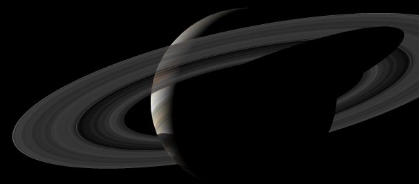
Note the shadow of the rings on the planet, and the way you can see the planet through the rings.
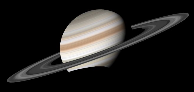
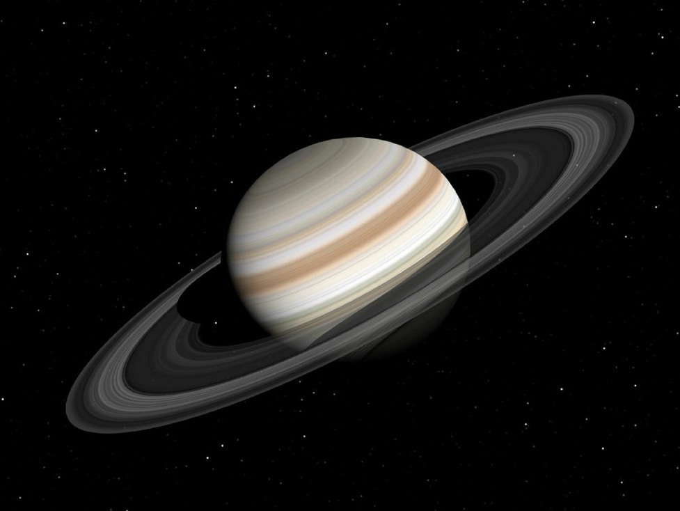
The end result.
OK, now we are done! Here’s an image of the final object. I have added a lens flare for the Sun, and used a stars plug-in to give a realistic star background.
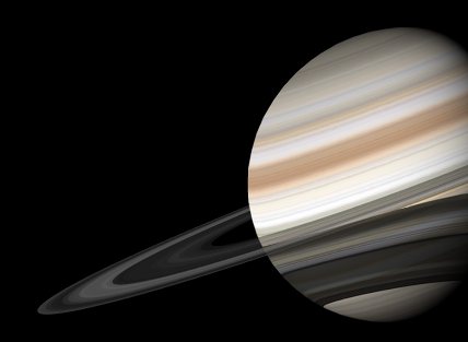
And this image shows you can get really close to the rings:
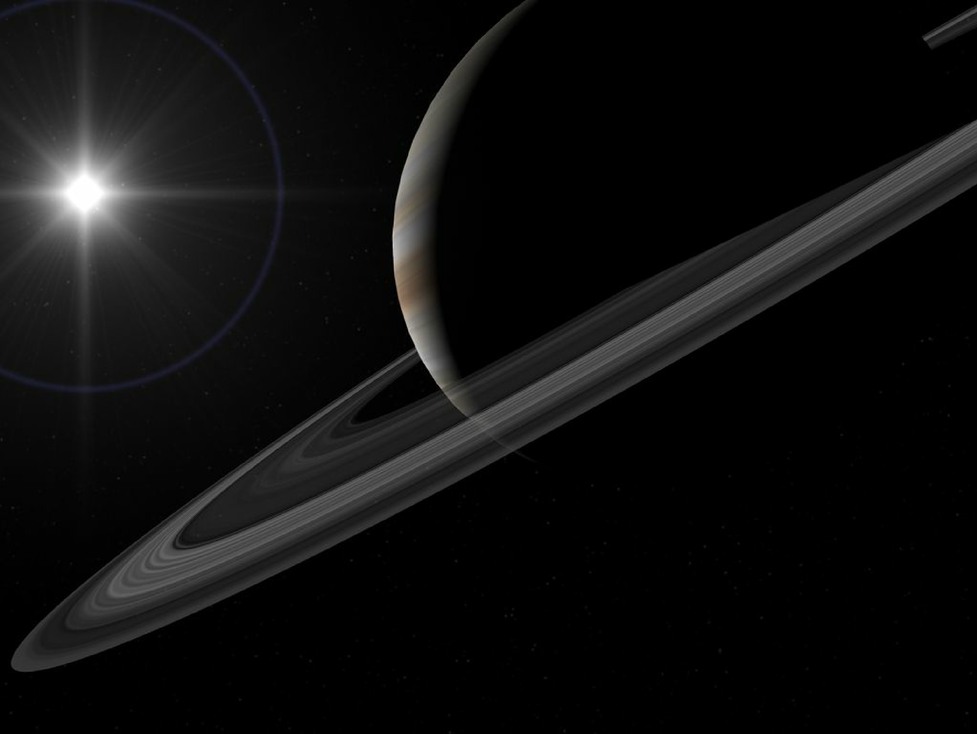
17. Notes on animating: Please note that the amount of fine detail in the ring system makes this a very difficult object to use in animations. You will probably need very high levels of anti aliasing for it to look good and move smoothly without shimmering. If your end goal is an animation, I strongly recommend that you use the smallest image maps you can get away with on the rings. If you are working at DVD resolution, maybe 300 pixels is good. Also turning ON pixel anti aliasing for the textures will reduce flicker, (at the cost of detail).
If you are animating, try anti aliasing of at least 11, and I find the Mitchell reconstruction filter (Camera Properties) works well.
Note! I am deliberately not including scene or object files, so you must make your own! I strongly suspect that people treat these files as free objects more than a learning aid.
Taking things further.
18. The main focus of this tutorial was the rings, as most people can work out how to wrap an image around a sphere. There are many sources of useful image maps for planets on the web, for example try the JPL planetary maps page http://maps.jpl.nasa.gov/ You can use the same tricks of adjusting the hue and contrast to turn the whole globe maps for planets like Jupiter into alien worlds that are all your own.
You could also have a planet with a gap between rings, (use 2 washers), for your spacecraft to fly through.