So, in part 1 I showed you how to locate and work with references.
Here in part 2, I’m going to work an example, the Mercury Atlas. I’ve done it in one long part again so it’s easy to print. (Handy hint! You may be able to print to PDF to get a portable version…)
I’m not going to give blow by blow instructions to build the model yourself, but you should see enough examples of techniques used to address common elements in modelling rockets.
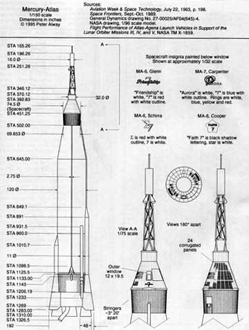
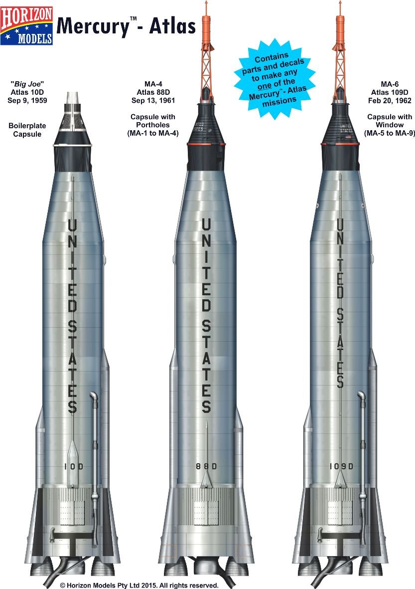
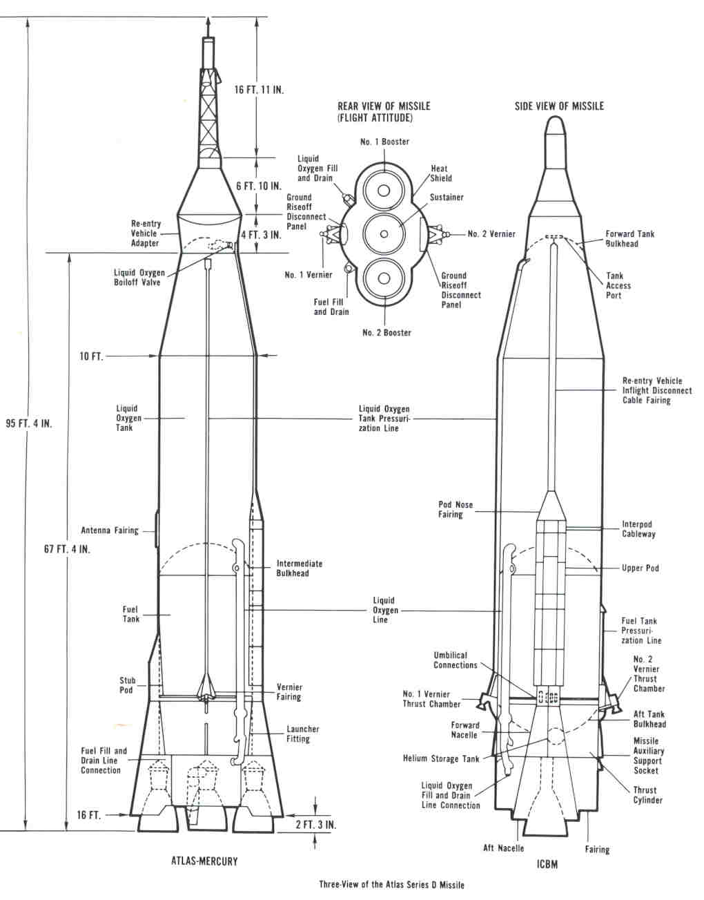
Now I have Rockets of the World, so I can use the dimensioned plans from that – small version follows, (deliberately too small to use, as its copyrighted).
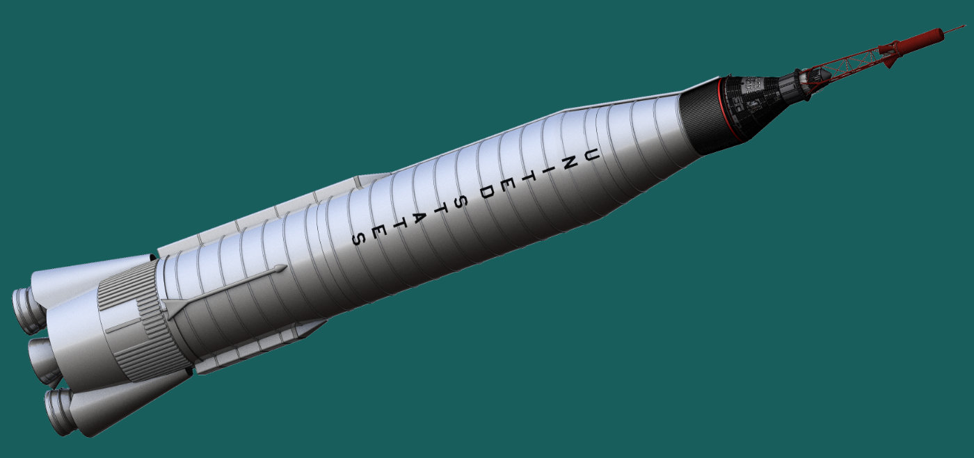
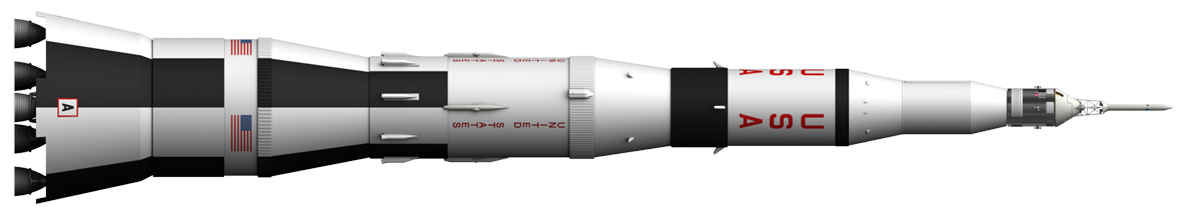
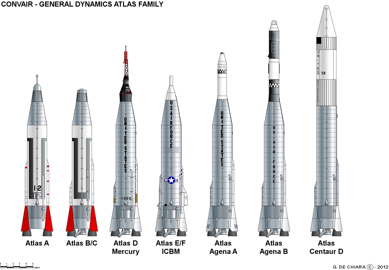
But you can do a good job without. Using methods described in part 1, I was able to locate some perspective free views, at good resolution. Click for a larger image:
So, let’s get ready to fire up the modelling software. As usual, I am using Lightwave 3d, but I’ll try and keep it as general as possible. I won’t be using any advanced techniques, so it should be possible to match this in most software. If you are getting started, take a look at the excellent free BLENDER software.
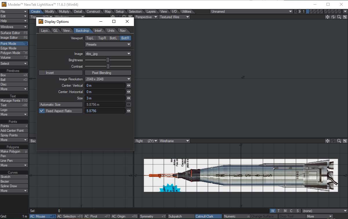
I want to put the perspective free images in the background of the modeller, so I can use them as a guide. Now if you have the various heights and diameters, you can model directly from that, but a visual check is always useful.
Ideally you want front, side and end views, but you probably won’t have the full set. Fortunately rockets are basically tubes and tapered sections, so you can get most of it right from one view. Those flared sections around the outer engines may be tricky, but lets’s get started on the main part before we worry about that.
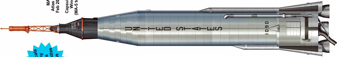
So I have rotated the rightmost image and cropped it out. For now I am going to focus on getting the shape right, and I’ll scale the resulting model at the end.
In Lightwave, this is controlled by the BACKDROP OPTIONS. You can load an image into each window, position it, and set it’s scale. The most important thing is to get it centred perfectly along the axis.
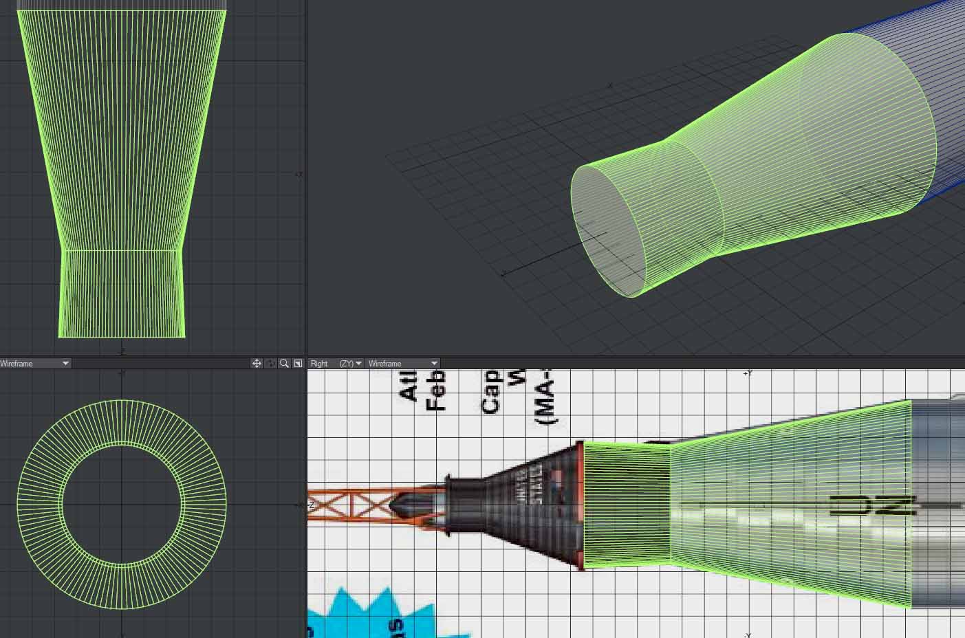
Next up, make the basic cylinder, and align it with the biggest straight sided section of the rocket, like this:
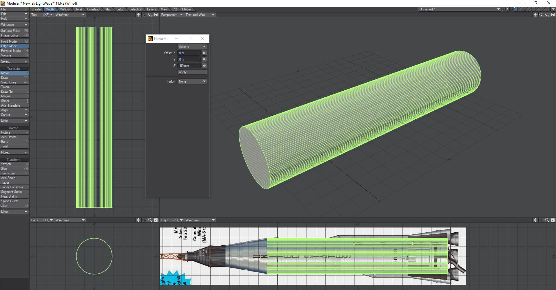
Zoom in to check the alignment is as good as possible.
Next up, select the top end of the cylinder, and bevel as required, using the backdrop as a guide. Interesting to see there’s a slight widening behind the Mercury capsule!
Now the Atlas is a relatively simple shape, most rockets have more bevels than this, but the idea is the same.
Texture cuts
At this stage I like to cut in the boundaries between textures. What do I mean by this? Well, often there are bands of colour, or ridges along the place where the stages separate, or bands with flags and logos. Cutting these into the polygons makes it easier to sort this out with a separate section for each map.
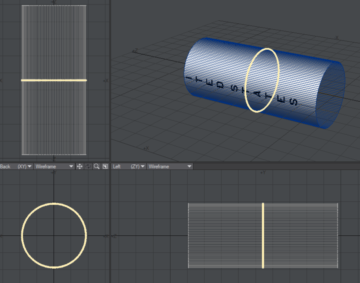
The most obvious ones here are the area with “UNITED STATES” written on it, and the area with the ridges near the base. (Technically these are called stringers, and reinforce the hull). here’s what I did, with arbitrary colours to make the different surfaces more obvious.
Rounding the edges.
One of the things that makes CGI look fake is really sharp edges. A bit of rounding can make a huge difference, particularly when it catches a highlight as the object moves.
Software generally has the option to smooth over the angles between adjacent polygons. If the polygons are large, this can spread the smoothing over a large area, and that will look wrong. making additional cuts close to the bends will limit this. I’ll do this as an example in the area where black paint meets the main hull.
The other method is to actually add geometry for the rounding.
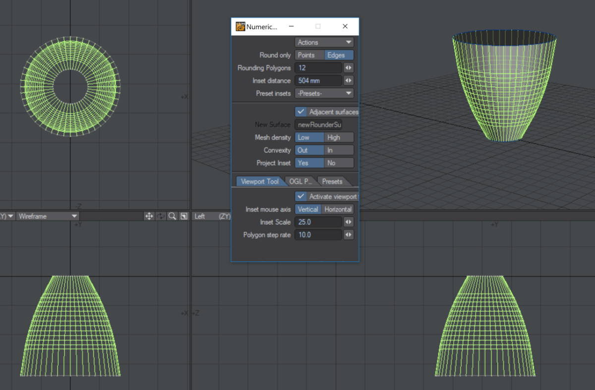
In Lightwave you select the edge you want to modify, and select “rounder” from the multiply tab. Note that rounder can be a bit unstable, so I recommend always saving before you use this tool. As you can see from the next screenshot, it converts the sharp edge into a smooth curve.
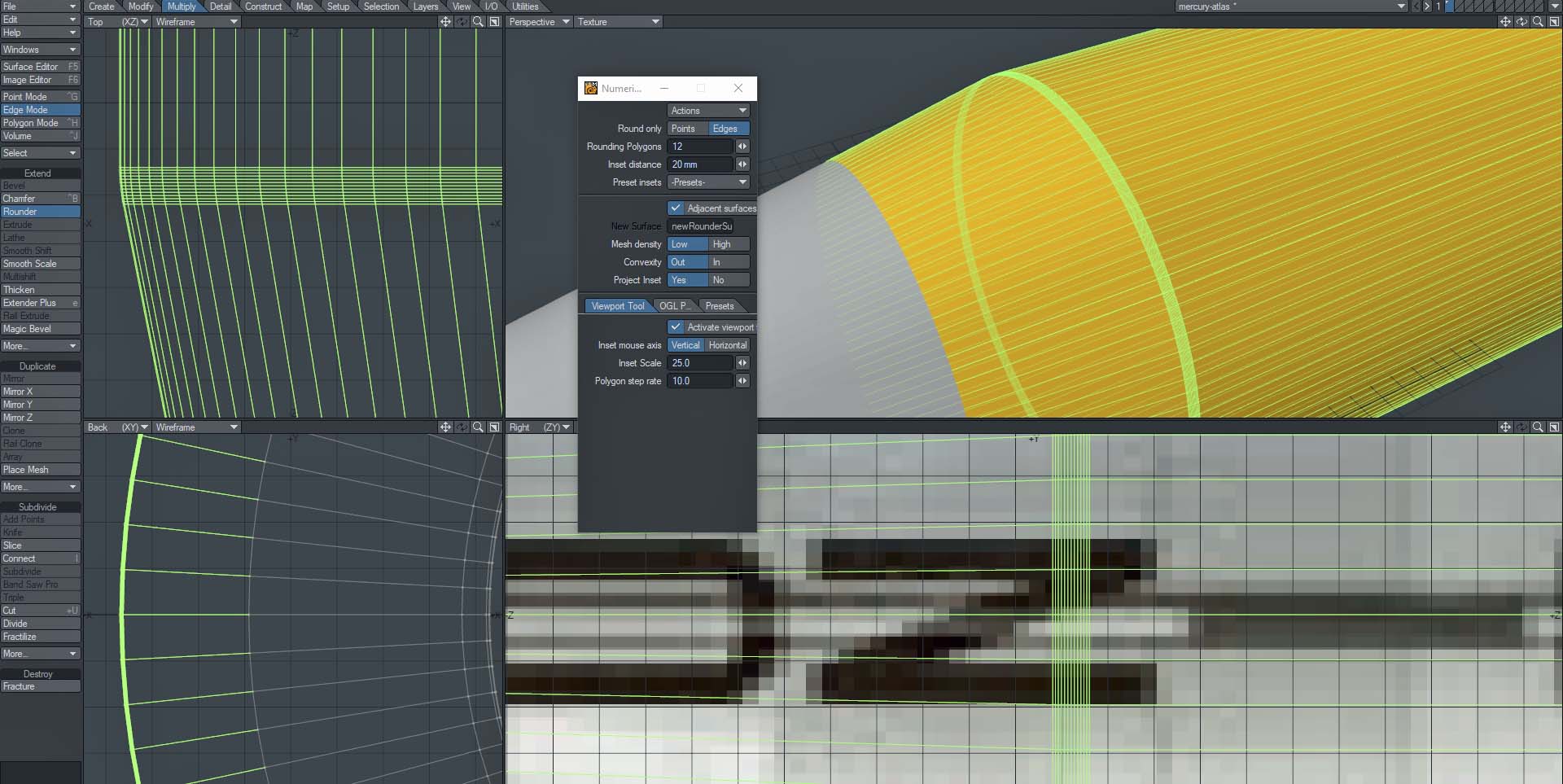
Lightwave is unusual with regard to smoothing over rounding, you can set the angle at which rounding occurs, and set it by surface. I find an angle of about 15 degrees works well in Lightwave as a starting point.
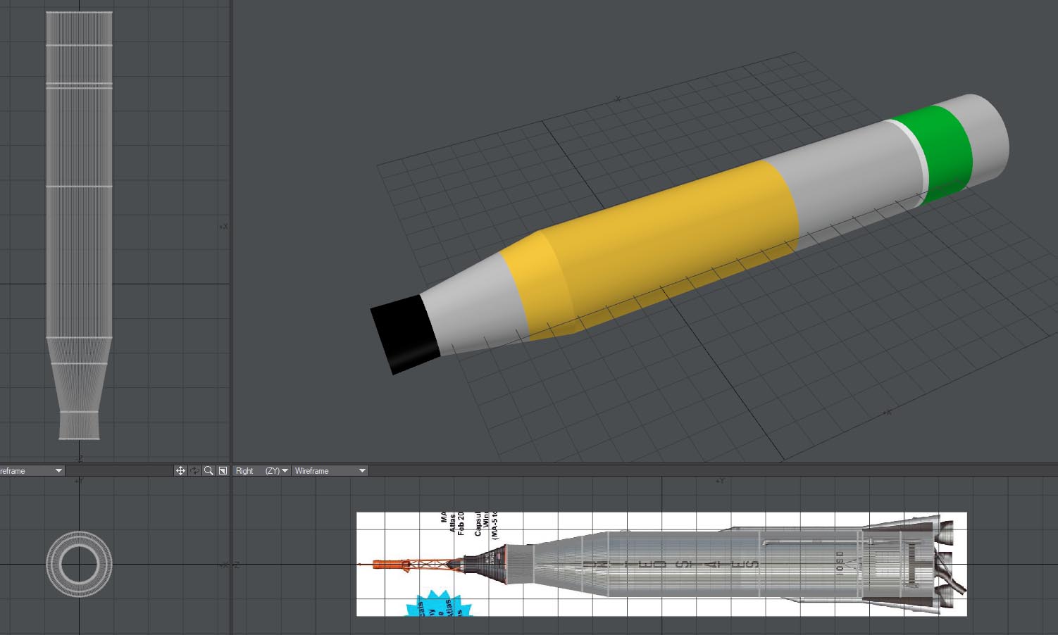
Now I’m going to change the surfaces to something more realistic, shiny metal. And add the Mercury capsule I built before.
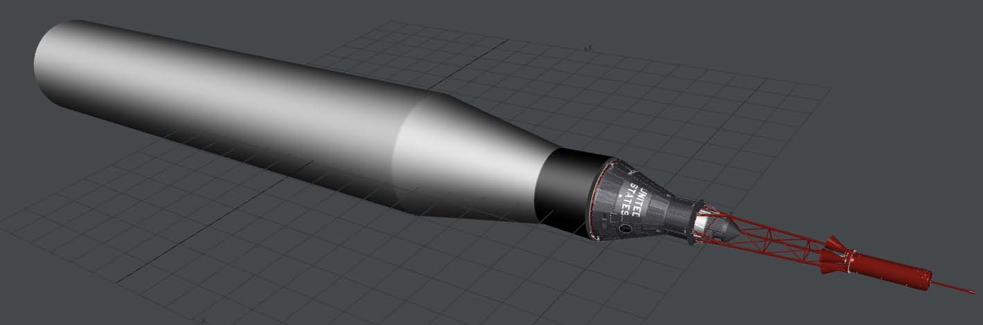
I’m going to start adding details now. Again using the backdrop as a guide, I have added the tubes on the lower sides, (shown in red for now), stringers around the black section, and a red rim at the top.
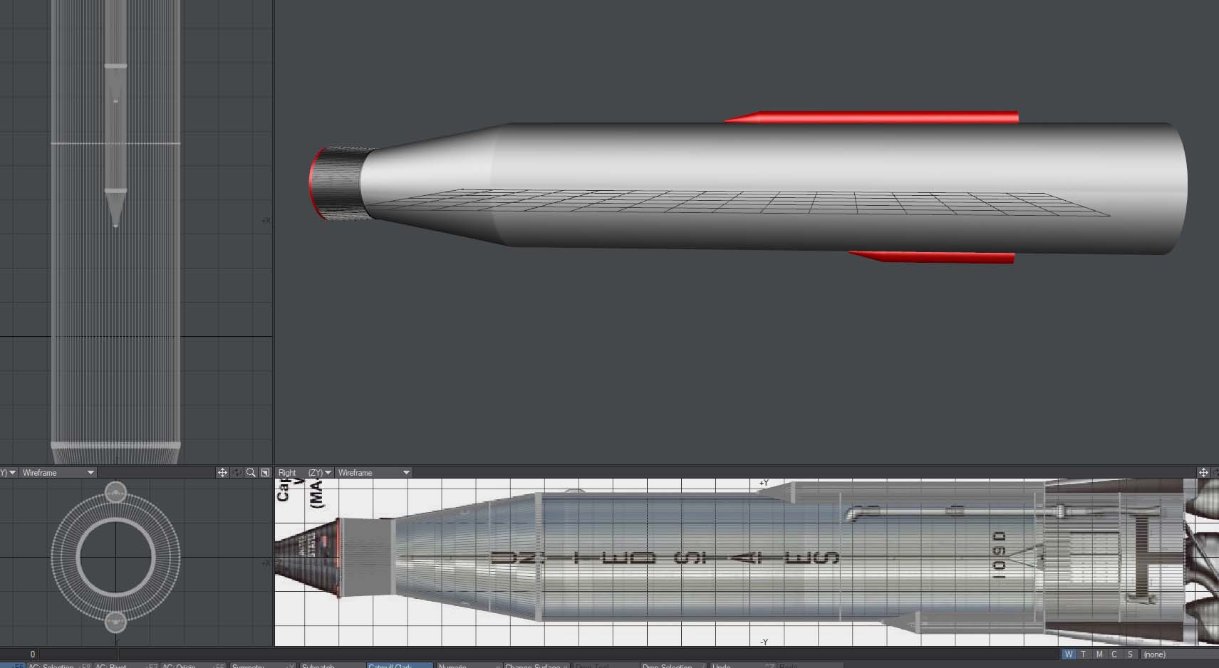
I’m not sure I have the number of black stringers exactly right, I think it is close enough. My research suggested 109 of them, which seems a bit weird! With 120 sides in polygons on the rocket I decided that was close enough so just selected them, and bevelled in and up a bit.
Similarly with the base stringers, I looked at photos and took a reasonable guess. All the same size to start with, I’ll shorten some as required later.
The shape of the base was not clear from publicly available pictures from the first pass, but a second run found something helpful:
This will also help get the other side pipes in the right place. To run pipes and conduits up the side, I normally do a completely straight one to start, then cut across the polygons with a knife tool, so I can then easily pull the sections snug against the hull. If necessary use a rounding tool to smooth out the bend.
If the pipes and conduits are not along a 90 degree angle, (so they are in profile seen against the side of the rocket from one view), I recommend building them in profile, then rotating them into place.
The Engines
Rocket engines can be tricky – if there are exposed twisty pipes that weave between each other, it’s really difficult to even understand the geometry, let alone model it. Fortunately in this case we only have the exhaust nozzle to model.
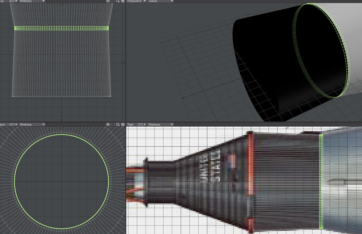
I generally start with a simple disk, and one bevel:
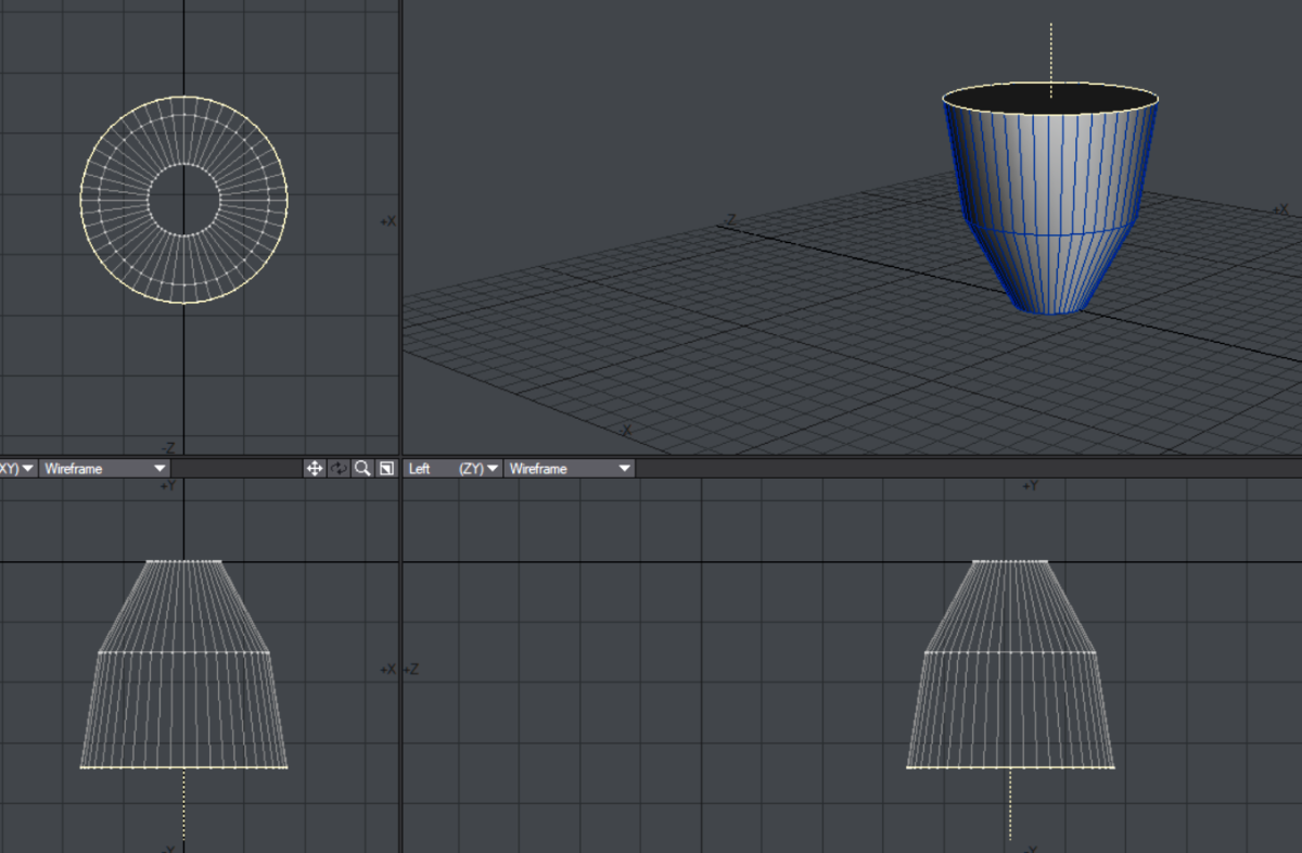
Go to edge mode, select the middle ring of edges, and apply rounder to smooth it off nicely, like this:
It’s unusual to get a well lit view into the inside of the engine bell, so you can usually just make a lip, set the surface to a very dark or black colour, and bevel in.
I’ll just mention here that the most common extra elements you will need here are a pipe down the side, (use the same methods you used for the main rocket), often connected to a pipe that loops around it – this is normally a method used to warm the cryogenic fuels before ignition.
Ridges around the hull
This can also be used to spin a pipe around the engine bell. I’m modelling the ridges with geometry for a couple of reasons – these days the polygon count is not a problem, it renders better, but mainly because it is very easy to adjust – if you are working on a constant diameter section of rocket, it is easy to adjust the spacing, or slide the ring up and down the hull.
I’m using the lathe tool to spin a disk around the hull, you may find a torus works better for you. Just be sure to have the same number of sections as there are polygons in a ring around the hull. You can adjust the prominence of the ridges by either adjusting the torus thickness, or making the whole thing slightly smaller or larger.
Panels / Hatches
These can be particularly tricky, as they often seem to occur on curved sections of hull, and not just cylindrical curves, but on tapering sections.
Here’s how I go about them.
The temptation is to do Boolean operations, cutting into the curves and making geometry that way. The problem is that this can easily lead to problems with the smoothing, 2 point polygons, and problem geometry. They are also almost impossible to adjust.
The trick of it is not to join them to existing geometry.
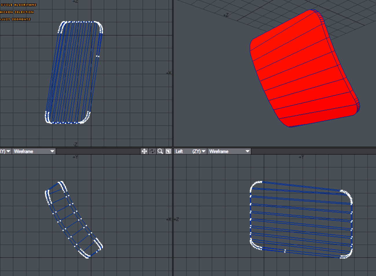
Start by copying the base hull polygons into a new layer. And make a ‘cutter’ as if you are about to cut into them, perhaps like this for a square hatch with rounded corners.
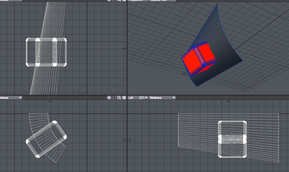
Stencil the box into the hull copy polygons, (In Lightwave: Construct / Solid Drill / Stencil).
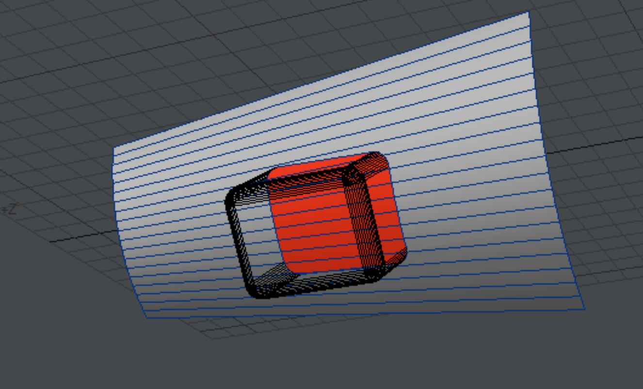
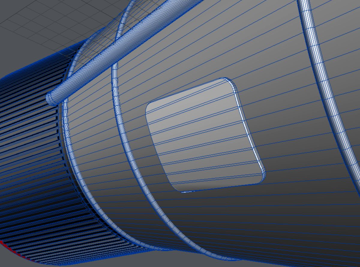
Next, cut away everything except the hatch polygons, (red in this case), and thicken the hatch slightly, (Lightwave has a dedicated Thicken tool). Like this:
You now have a hatch which does not spoil the polygon flow, and that stands slightly proud of the hull, to look physical and solid. You can also clone it around the hull if there are several of them. For a finishing touch use the chamfer or bevel tool to add a sloping edge that will catch the light nicely.
Note that there is not actually a hatch like this on this particular rocket, so you won’t see it in my finished version.
Summary.
I hope you will find these techniques helpful – here’s the finished result!