
Identifying N-1 variants. I mentioned this briefly in an earlier post, which featured some images I stitched together from video, but here it is in a bit more depth.
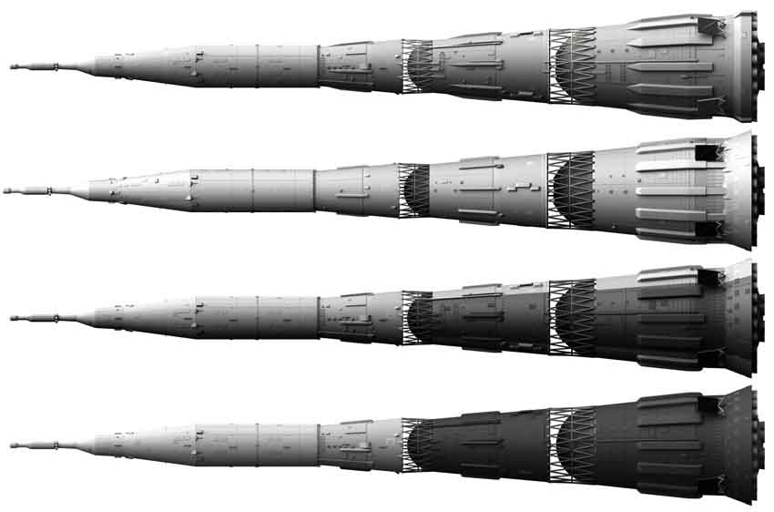
You are generally trying to distinguish between 5 different N-1 variants in photographs, the four that flew, and the weight model. This is most easily done via the colours, though there are several other differences.
This post is not about ALL the differences between the variants, just about how to tell which rocket is which.
N1-3L, the first flight.
This is easy to identify, as it is the only one with entirely grey first and second stages. The third stage is half white, with the white part facing upwards on the transporter, which is the side away from the gantry once the rocket has been erected. It was transported to the pad in winter, and there are photos of it with snow on.
Note that there was no green on any of the N-1 variants! This is a widely held misconception, as many museums show it as green, (including the London science museum, and many Russian museums too). Olive green was only used to camouflage missiles, (and green would make lousy camouflage in Baikonur at the best of times). This error has spread to the point where photographs have been tinted to make them look green). And sometimes it was just poor quality film stock.
It was the only version without a heat shield on the base, but bare metal.

N1-7L, the last flight.
The next easiest variant to identify. This is the only version that was painted completely white. You need to be careful though – the darker sections of the N1-5L and N1-6L faced towards the gantry, making it hard to spot in photos once it has been erected on the pad.

Fortunately there are a few other key differences which help.
Most obviously, the distinctive fuel line covers have been streamlined, so the leading part comes to a point. This is on all 3 stages, and if you look carefully is not too hard to spot.

Also, the N1-7L has the grid fins around the base of the first stage painted white. They are dark or black on all other variants. Plus, (in the same area of the rocket), the lower edge of the first stage skirt goes straight up and down, rather than the acute angle of the other versions.

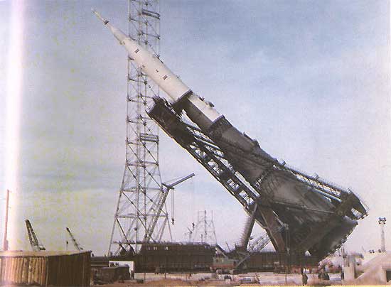
The weight model. N1M.
(Sometimes N1-1M). This was a full size model, used to test the launch systems, such as the ‘Grasshopper’ transporter. As the program developed, it was adapted to keep pace, but is most often confused with the N1-3L or the N1-5L. The clear identifier is at the very tip of the rocket, as the weight model does not have a proper escape system, just a stalk. Note how there’s no wider section at the top of the weight model.
Here is perhaps the most famous photo, two N-1’s at the pad!
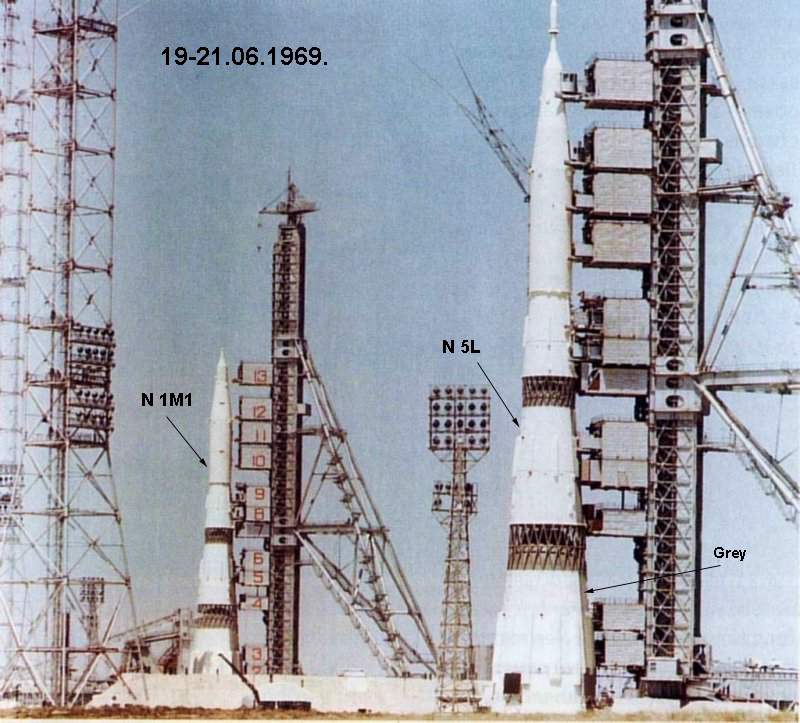
But if you look at the nose, you can tell that the rear rocket, the one on the left, is the weight model.
N1-5L and N1-6L.
This leaves us with the two most tricky versions to distinguish, the 5L and the 6L.
Both have a darker, grey sector on the first two stages, and in both cases it is on top of the transporter, and towards the tower once upright. The grey edge is tricky to spot, so note that the top of the fuel tanks, visible through the interstage, is dark, compared with white on the N1-7L.
So how to tell the difference?
There are two key differences, though they are not easy to spot in some cases.
The fuel line covers of the 6L first stage are distinctly different at the bottom. Rather than being sealed, they are cut off, and a fire extinguisher system sticks up into the opening. There’s one fairly clear picture of this.

The 5L fuel line covers are sealed and rounded off, in a similar manner to the N1-3L.
Here’s my CGI version of the 6L, to show you more clearly:

The other difference is harder to spot, and it is that the dark sector is 90 degrees on the N1-5L and 120 degrees on the N1-6L. Given the poor quality of so many photographs, this is less helpful than it might be. But if you can compare the line of transition between white and grey with the grid fins, then on the 5L this line passes right through the middle of the grid fin, as seen here:

Complications.
Be aware that some public photos have been flipped left to right, and that photos from inside the factory may not have all the components added.
More Info?
I did almost all the graphics for the book “N-1 for the Moon and Mars”, by ARA Press. Copies also sometimes crop up on Amazon.
Hello, I read the ARA Press book on the N-1, in which you made line drawings of the L-3 composite spacecraft. I found those drawings very useful.
Have you published similar drawings of the L-3S version that actually launched on N-1s 3L and 5L on February and July 1969? I am mostly interested in the shroud joining the L-1S spacecraft to the Blok D, the L-1S itself, and the electronics package that was carried within the shroud instead of the LK lunar lander.
Thank you
No, not aware of any good info on that. Sorry!
On a more positive note, I plan to revisit all major elements I did for that book over the next six months, check for new information, and add more detail where I can. (I’m already sure I can improve the launch tower, and plan on doing the internal rocket structure as well.
I’m also thinking I just might be able to get enough info from shots of relics to have a shot at the N1-8L!
Nick
Hi, may I ask a question?
The 3L,5L,6L,7L all are the same length: 105.3M( 105.286M)?
As far as I am aware, yes.
It’s worth noting though that the launch tower was adjustable – the “access sheds” or whatever you call them could be adjusted in height, and the plates on the upper hull of the rocket, (l3 section), to clamp it in place could handle a difference of something like 15 cm.
thanks very much. thanks!